Hon. Sec: A.R. Thomas,
EDITOR: D.J. Irwin.
3.
Contents
Address change
Garth Dell, 5 Millground,
Withywood,
3.
*****************************************
Thanks to Bob Bagshaw and John Churchward for gifts of
caving and climbing publications to the Club Library.
Working Weekend
September 6/7, 1969.
The last weekend that was set aside for work on the Belfry
had just about nil support from the Belfry regulars. Another weekend has been booked and will be
closed to all except those actually working on the building. Please come along and give John Riley some
support. There is plenty for members to
do repairs to the roof (some though are being done at the moment) and
ceilings; water traps need assembling into the sink units; new door needed on
the toilet main entrance and many smaller jobs inside the Belfry. DONT FORGET THE DATE AND COME ALONG AND LEND
A HAND.
Burrington Atlas
Work is proceeding at a reasonable rate on the Caving Report
The Burrington Atlas. To illustrate
the publication we are looking for early photographs of caving parties and the
caves. If any member has any prints or
negatives I wonder if they would let Dave Irwin know as soon as possible?
G.B. Cavern
It is reported that there has been a sizable boulder
movement between the ladder Dig and Bat Passage. This area of the cave is being closed to all
parties until the U.B.S.S. have completed their inspection of the area. Reports of boulder movement have been made
from time to time since its discovery in 1965.
Cavers Bookshelf
By Roger Stenner
The
Speleological Society Journal, Volume 1. No.4, May 1969. No price
stated. (In B.E.C. Library).
This edition of the Journal is unlike so many other club
publications in that only one of its 46 pages consists of club news unlikely to
interest anyone outside the club. The
Journal contains a review of mines in the Coniston area of the
Mines of Long Rake which is not of much value without part 1 (No.3 in B.E.C.
Library). A mine survey is included
which uses the misleading practice of representing a passage by a single line,
presumable because of a poor choice of scale. The script contains no details of
the survey. Reviews, letters to the
editor (Biospeleological notes; Tratman on the Doolin Cave System, Eire),
article Pioneer Speleologists in
Derbyshire (largely a biography of J.W. Puttrell) and an article on University
Speleological Societies (discussing problems peculiar to University Caving
Clubs) make up the Journal together with an article by S.J. Thompson, Karst
Water Analysis, which merits further discussion.
The article refers to more than 50 chemical (and physical)
Qualitative and Quantitative analyses for major constituents and trace
constituents of Karst Water. Indicating
the sort of determinations that chemists can carry out, it may provoke
non-chemists into prodding any chemist in the club into action, but the
limitations must be born in mind by all readers of the procedure for a
particular determination their article will not and cannot take the place of a
spell of a time in a library with Chem. Abstracts and Anal. Abstracts.
It is strange that a review of modern techniques should fail
to mention X-ray fluorescence spectrometry for detection and determination of
trace elements, and no procedure is given for routine measurement of sodium and
potassium (present in more than trace concentrations). Procedures which turn paper chromatography
into a quantitative techniques were not mentioned, and although procedures for
determinations of minute concentrations of chloride and sulphate were referred
to, there was nothing suitable for the larger concentrations usually
encountered on Mendip.
The key question of interpretation and uses of trace element
analysis was raised. However, most
techniques mentioned are also suitable for analysis of stream-bed deposits,
investigations which (since streams are made to flow upstream only with some
difficulty) may be of value in spite of flooding re-deposition.
Recent Additions to the Club Library
By Wig
To attempt to review every publication that reaches the club
library would fill the B.B. for many years. Instead Im taking the publications as they were handed to me by Dave
Searle (Hon, Librarian) and hope that I pick out articles of interest to
members.
SWETCCC Speleo, vol.7 No.2 contains an interesting article
entitled Swildons 51 followed by Free Diving and discusses what can be
done, if anything, if a companion gets into trouble when free diving
sumps. The Royal Forest of Dean Caving
Group have published an eleven page report on their trip to
1968. Interesting accounts of several
trips. W.S.G. Bulletin Vo.6 No.3
(May/June 1969) odd notes from
Caving and the Unconscious (see June B.B.) and an unnecessary Caving
Glossary. C.R.G. Newsletter. No.115
(Mar. 69) has more information on the
of Kjopsvik (with surveys) and Foreign Language contents (a-c). C.S.S. Newsletter Vol.11 No.5 The Western
Taurus Mountains (includes surveys of area and
only. Axbridge Caving Group
Newsletters Ap. 69; Mat69 Dangers of Hyperventilation by O.C. Lloyd
(article in Spelio mentioned above in Spelio). June reply to Oliver Lloyds
letter in May issue. B.S.A. list of
members (Jan. 69). W.S.G. Vol.6 No.2
Pronunciation of Welsh words and reports of the Pengelly Lectures held at
A.G.M. of C.N.C.C. Spelio (SWETCCC) Vol.7 No.1 contains notes on the survey of
Swildons North West Stream Passage (incl. survey to same scale as Willie
Stantons). For the Spanish speaking
members of the club the Bologna Speleos publication Sottoterra contains many
surveys and useful lists of publications received by their club. (Nos 19 and 20 April and August 1968), also
No.21. Speleon (university of Oviedo
(Vol.16 Nos 1-4) contains a mathematical treatise on resistivity method of
locating caves and a long article by Jimenez of Cuba. July issue of Climber; the June/July
Rocksport contains an article of interest not only to climbers but to cavers
Advances in Safety Techniques; June Climber;. Northern Caving (Northern Cave Club) Vol.
No.1; Care of Lamps and Padirac. Also
interesting account of Meregill by E.E. Roberts (1908). D.S.S. Monthly Journal illustrates how active
the club is at the present time and their Journal includes many snippets of
useful information regarding both caves and mines of the
area as does the monthly bulletin of the G.S.S.
Without any doubt the most outstanding publication received
this year is from the U.B.S.S. with the jubilee issue of their Proceedings,
Vol.12 No.1 contents include History of the Society in
Central Mendips; The Society in
of
of course the Archaeological reports.
Drawing Of
Accurate
Cave
By D.J. Irwin
All passage detail has to be related to all the survey
stations in the area being detailed. Using the data collected in the cave the outline of the passages can now
be drawn into position. But here we find
another problem how much of the information is included and what is omitted;
further what is collected in the cave?
Up to the moment the survey lines have been drawn onto the
master drawing but before notes are given on how to add the information it
might be as well to transfer ourselves between the cave and the drawing board
and examine the detail that is required and how it should be shown on the plan,
elevation etc.
Surrounding the survey line is the passage outline. This should, as near as possible, be surveyed
to similar standard of accuracy as the survey line. Normally a closed traverse should be better
than 2% (though this will naturally depend upon the traverse length).
The amount of detail to be collected will depend at the
scale at which the draughtsman will draw the survey. Two points determine the scale (to remind
ourselves for a moment) -1) the maximum size of paper available to the
draughtsman and 2) the minimum passage width that can draw accurately without
specialised drawing equipment.
We should also consider the point of making the survey is
our finished drawing going to be published for the general caver or the
specialist or both? Lets assume that
the finished print is to be for the specialist; as we go along the survey for
the general caver will also be considered.
It is obvious that the larger the scale the more detailed
the survey in terms of the passage outline etc. This will mean that the surveyor will need to
collect much floor and wall details including solution pockets, climbs, pools
and any other special features.
As an example lets assume that the cave survey is being
drawn at 1 = 20ft. What information is
to be collected? The smallest width that
the surveyor/draughtsman can draw at this scale is a true dimension of 1ft.
(0.05); thus all detail collected in the cave must be greater than this. As the cave passage is a three dimensional
object it has to be shown in the three plans: – from above (plan), from the
side (elevation) and through the cave showing passage relationship with their
respective height values. Similarly at
any on point along the passage length there is also another group on two planes
that must be taken into consideration a) passage height and b) passage width.
Passage Width
The width of a cave passage is something that proves
difficult to define and Ive met no-one that can state this so that it covers
all types of passages met with in caves. When drawing the passage section the width can be shown without any
difficulty but the drawing of the plan often produces problems that are not
easily overcome. Take for example a
narrow sloping rift as found in the Catgut Series in St. Cuthberts
Swallet. It is barely more than 2ft.
wide over most of its length but the horizontal distance from top to bottom is
some 8ft. Does the draughtsman draw the
passage as being 8ft. wide or 2ft. wide? Another type of passage met with quite often is the T shape. If the passage is say 10ft. high, 10ft.
across the horizontal bar of the T and 4ft. wide in the trench what is shown
on the plan? Swildons streamway below
Barnes Loop displays another common shape of cave passage. A vertical rift narrow at the bottom but very
wide at the top. Is the full width of
the passage at the top shown or the width at the bottom?
Among the many other problems associated with passage width
is the minor variations near the floor level. How are these to be taken into account? A good example of this type of streamway is found below Plantation
Junction and the Beehive Chamber in St. Cuthberts. Here the passage commences as shown in figure
8 and gradually forms into a high, narrow rift. The shelving at the start is well marked; near the stream level on the
right (facing downstream) are several ledges 1 – 1¼ wide while on the left a
high level ledge tapers down to the streamway. Are all these variations to be shown on the plan?

As can be seen there are many variations of the same
problem. How is this to be tackled by
cave surveyors ensuring that they collect sufficient information for the
draughtsman to lay in the survey and also to ensure some form of
standardisation in survey presentation? What is to be shown on the plan, elevation and section?
One of the requirements for a cave survey (1) is to enable a
caver to get sufficient information to get him around the cave. As this is an accepted fact agreed by all
cave surveyors then it is not an idea to show on the survey what is seen
by the caver when he is travelling through the passage? In other words the draughtsman shows the
passage width along the cavers path. In
the case of the sloping rift in the Catgut Series which in this cave is
normally traversed along the floor level the plan will show the width at a
point used by the cave i.e. 2ft. ignoring what happens above or below this
point; these variations can be easily shown on the elevation or passage
section.
If we accept the cavers path for the passage width on the
plan the passage profile at the point becomes very important. Depending on the scale of the drawing and the
ability of the draughtsman to draw accurate within the tolerances suggested
above then the information gathered in the cave must be sufficient for him to
show all the various changes at the cavers level. Where the wide section of the passage (figure
8) drops to the cavers eyeline then this can be shown as a break in the wall
outline as suggested in figure 9 illustrating a ledge entering the cavers
eyeline above. There are not many
variations that break away from the basic rule suggested above but there will
be occasions when the upper parts of the passage will have to be shown on the
plan when a high level has to be shown when the cavers route to it is by a
climb along ledges or up the wall.
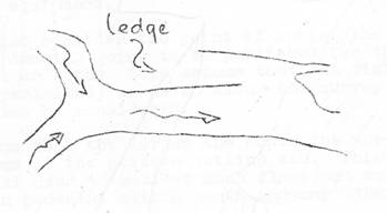
FIGURE 9
Figure 10 illustrates the ray method of detailing large
and complicated passages and crawls etc. It will be noted from the figure how the detail is related to the survey
station with no difficulty. The author
favours this method where the passage outline and prominent features are
surveyed in a similar manner to the main lines. All value read on the clino above 10o are then calculated with a slide
rule and are then plotted onto the drawing using a protractor to plot all the
points. The points are then joined
together rather like childrens follow the dots puzzles. The calculation of the clino values become
necessary when drawing at a scale of 1 = 20ft. or larger. Estimated distances can involve enormous
errors some as large as 30%. In a
passage of say 15ft. wide or more, errors of 5ft. or so cannot be tolerated in
an accurate outline survey. It is even
more ludicrous when plotting to the nearest foot and there are errors in the
passage width of maybe 5ft. and over. For the 1 = 20ft. (1/240) scale surveys all distances should, for
detailing purposes be measured to better than ±6.

∆ Principal survey stations
Sub – lines
___ Main survey lines
FIGURE 10 Detailing
chambers and very wide passages.
No view can be expected to show any changes in passage
heights, the existing avens etc. This
gives the reasons for the need for elevations and passage sections. When the passages are all drawn in position
and the outline completed a quick glance will show the complicated portions
that will need clarifying (figure 11).

FIGURE 12 1 – 9
Passage Sections
Related to the plan and elevations are passage
sections. The passage section plays an
important role when presenting a cave survey equal in importance to either of
the other views. What cannot be shown on
either plan or elevation must be shown on the passage section.
There are two extreme methods of showing changes of passage
section; they are: 1. to draw the sections at regular intervals along the
survey line or 2. to draw passage sections at all survey stations.
The second suggestion omits changes of passage shape between
stations and consequently does not give sufficient information. On the other hand the first suggestion shows
all the changes of passage shape will involve a tremendous amount of repetition
where passages are constant over their length. A compromise must be struck and a general rule observed. Passage sections are required at all points
where there is a marked change in passage section. This might well occur every few feet along
the survey line or it might be sufficient to show the section only at the
survey stations.
There are two ways in the section can be presented on a
survey 1. Draw all passage sections alongside the survey line on either plan
or elevation or 2. Draw all the passage sections in a separate part of the
sheet. It is recommended that all sections
be drawn as in 2. This is because the
plan and elevation may well be complicated or maybe drawn at a small scale that
will prevent the draughtsman placing the sections along the passage line. By working to 2 the draughtsman prevents
cluttering the views bearing in mind that names and notes will have to be added
to the various views.
As stated under Passage Outline the plan will show the
cavers path what happens at a higher level in the passage will be shown in
the passage section. Definite solutions
have not been stated in any previous notes on the subject and an attempt is
made in figure 12.
Sections 1, 2 and 3 (fig.12) are straight forward and need
no comment. The basic rule being that the plan shows the passage width where
the caver passes and the section lines are taken through this point on the
passage section.
Passage sections 4 & 5 illustrate a stream passage with
an upper meander forming part of the passage (e.g. Easegill and Tunnel
Systems). Where this occurs and both are
used by the caver then the survey lines should be taken through both levels and
detailed as separate passages. The fact that both may be joined by a rift is shown in the section of
the passage; an attempt to show the rift feature on a plan would confuse the
user of the survey because the additional lines that would be required to show
the rift. The elevation, if scale
permits, can be shown with a dotted line representing the upper traverse line
of passage. As the section line on the
plan should be annotated as shown in fig.12, so it is important to remember
that the passage section must be complete with the section line at the point at
which the passage is cut. In the past it
has been a regular practice to number or letter the sections. Letters tend to become clumsy where a large
number of sections are involved so use numbers. For example 1-1, 2-2, 3-3 OR 1-1A, 2-2A
etc. A final point indicate the
direction along the passage that the section is being viewed upstream or
downstream (figure 13). Do not draw the
section line through the plan or elevation as this will trend to confuse the
user if the passage detail is complicated (figure 14).
Hidden Detail
Quite a number of instances occur when one passage crosses
another the vast majority are simple but occasions arise when a cave has
several levels one on top of another. The numbers of combinations of dotted lines need to be kept to a
minimum. Figure 15 will help solve some
of the problems. If however one is
preparing a detailed map for the cavers and the draughtsman intends to show
floor deposits and generally presenting a pretty picture of the cave then
displacements should be contemplated.
Detail Required On An Accurate Outline Survey
A summary is listed below: –
1. All vertical changes in floor level grater than
5ft.
2. Permanent survey stations. The height is given in feet above Ordnance
Datum. This value is obtained by
determining the O.D. level of the cave entrance and subtracting the depth of
the station in question below the cave entrance e.g. cave entrance height
780ft., depth of station below entrance = 140ft. then O.D. of station
= 780 140 = 640ft.
O.D. (See figure 16)
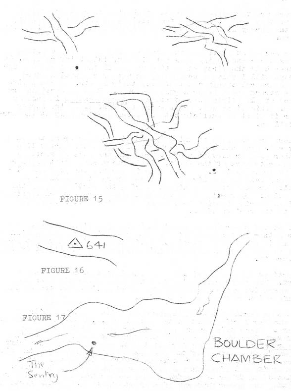
3. Names of passages and chambers. Print all names outside the cave passage
outline. To place names and notes inside
the chamber or passage will clutter the survey. Names of individual formations and other prominent features should be
added in a different print and arrow drawn indicating their position (figure
17).
4. Other features are shown in figure 18.
If the scale of the survey is large say 1 = 10ft., then all
of the above notes may be added whenever required. O.D. levels can be marked at every survey
station. On the other hand should the
scale be 1 = 100ft. then passage widths will not allow much to be added within
the passage outline. Hence it will only
be possible to mark O.D. levels at every principle junction or at selected
permanent survey stations.

FIGURE 13 FIGURE
14
Tracing
Having decided the layout and detail to be included on the
survey the final negative or original can now be traced. On what ever material is decided (detail
paper, permatrace, linen etc.) trace the grid lightly in pencil; this will
ensure that the grid lines to not detract the eye from the bold outline of the
passage walls or become mistaken as part of the cave outline in the various
views. When finally inking the grid
lines it is preferable not to take the grid lines through the views but leave
them outside the cave outline.
The thickness of the passage outline for the various scales
cannot be rigidly fixed. The complexity
will not often allow thick outlines to show clearly. To assess the best thickness of outline
produce several tests trips of the most complicated section of the cave and
choose from these. If the result gives a
clean neat appearance and above all, is easy to understand all is well; if on
the other hand the appearance is cluttered then try a thinner pen. A good reason for not making the outline too
thick is that when they are drawn close together an optical illusion will make
them appear closer together than they really are. When tracing the pencil original, ensure that
the inside of the pen follows the line thus ensuring that the passage width
remains true.
Whatever scale the survey is being drawn the following line
thicknesses will help keep the outline bold and still identify the passage
detail.
Passage outlines = 1 (e.g. No.4
U.N.O.)
Pitches, ledges etc = ½ (e.g.
No.2 U.N.O.)
Streams, slopes lines, arrows etc
= ¼ (No.1 U.N.O. or mapping pen)
The most convenient method of lettering that is neat and
easy to apply is Lettraset a form of rub-on stencil; failing this UNO
stencils give a neat finished appearance. The advantage of Lettraset is that it can be obtained in many types of
characters giving the draughtsman plenty of scope for variety of distinctive
lettering (passage names in capitals, names of features in lower case
etc). Remember it, there is nothing more
unsightly than bad printing however well the survey has been drawn. A good example of bad presentation and
lettering is the newly published survey of Lamb Leer included in the Lamb Leer
Report; the outline has been drawn with a nibbed pen, the lettering uneven,
appearance looks cluttered (e.g. O.D. value by main pitch) sections displaced
down and away from their correct position without and notes and so on.
Title Block
Many a survey up to the present time have not collected the
various bits of information together on the sheet to a focal point where all of
it is gathered together. A title block
will do this and also help maintain a uniform method of presentation.
Scale Bar
It is recommended that all scale bars be given in metric and
feet equivalents. It is certain that
sooner or later the metric system will be fully with us in this country and so
it is desirable that a metric bar scale be incorporated now to prevent change
to the scale bar later.

Final Note
Ive deliberately left out of this article details of the
various types of drawing instruments that can be obtained on the market and
full details of the special surveys (geological etc) that may be produced from
the cave survey, nor have I mentioned details of the survey report all of
this can be found elsewhere in caving literature. A full reference list is to be found below
for further reading and nearly all are to be found in the B.E.C. Library.
D.J. Irwin
4 Feb. 1969
References:
(1) BEC Caving Report no.12 Presentation of Cave
Survey Data by S.J. Collins, page 9 section2.
(2) M.S.C. Publication (yet to be published)
(3) As Ref.1
Other publications on various topics of surveying: –
Club Journal No.89 Accuracy of a Cave Survey by D. Warburton.
Shepton Mallet Caving Club No.2
Series 4, Traverse closures.
Surveying in
B.E.C. Caving report No.1 by S.C. Collins.
U.B.S.S. Proc. Vol.6 No.2 Survey of G.B. Cavern.
C.R.G. Transaction Cave
Surveying.
Monthly Notes No.27
By Wig
East Twin
Members have been over to the cave and inspected the washed
out rift mentioned in the August B.B. and confirmed the reports that the
passage leading off at the bottom is some 35 40 deep. This is particularly interesting as it now
represents the lowest part of East Twin. The first 20 is vertical and the general section is elliptical, about
6ft. long by 2½ft. wide. Two small
passages lead off to the left but become impassable. Beyond the 20ft. rift, the slope of the
passage eases to about a 45o slope and becomes extremely tight. Both John Riley and Wig could not penetrate
more than a body length into this passage. Roy Bennett and Martin Hauan then had a go, Martin reaching the end
reported that the passage was diggable but very light. Banger Bennett hopes to improve this by
opening a bypass around the back of a fallen boulder. The result has not yet been seen to enable to
decide whether to proceed with the site or not. The foreman at the sight was our Tacklemaster who viewed the entire show
from the top of the rift at first and towards the end from a very safe distance
outside the cave!
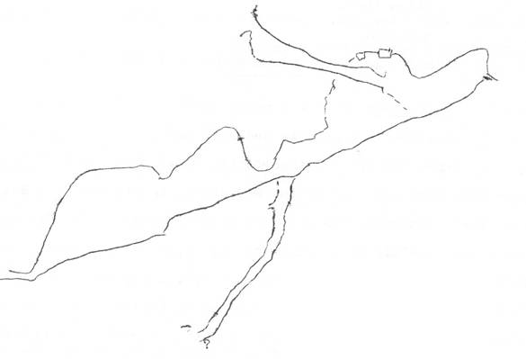
Sketch elevation of the opened passage. See BB No. 250 for further details of the
East Twin survey.
St. Cuthberts Cerberus Series.
The extension off Cerberus Rift has been attacked with
chisels to no avail; stronger measures are being planned. On a recent visit to the site a cool friendly
draught was striking one in the face.
*****************************************
BALLOT PAPERS will be in the post shortly to enable members
to elect next years Committee. Make you
choice and return the paper to Alan Thomas as soon as possible if not before!
As is usual during this time of the year one starts thinking
about next years Club Committee. The
position at the moment is not very clear but as the closing date for the
nominations draws near perhaps I might copy Alfie, who a few years ago
published a potted background of all members standing for the Committee. Andy MacGregor (1968-69) Caving Sec) and
Malcolm Holt have both resigned their posts on the Committee and so will not be
re-nominated with other seven. So, for
the benefit of members who are not around Mendip often, or those that have a
poor memory for names, heres the list or runners: –
Bob Bagshaw 168-69 Hon.
Treasurer.
Alfie Collins – past B.B. Editor and Committee Chairman; LTP bod.
Garth Dell past Hut Engineer.
Chris Harvey Belfry regular; active caver.
Dave Irwin B.B. & Caving Report Editor; Committee Chairman 1968-659;
active caver.
Jock Orr Belfry regular; interested in Belfry site.
Norman Petty Tacklemaster 1968-69 (hasnt reached his 1,000ft, of ladder
yet!).
John Riley Hut Engineer 1968-69; active caver.
Alan Thomas 1968-69 Hon. Sec; organiser of Ahnenschacht expedition 1969.
Gordon Tilly Minutes Sec. 1968-69; handles production of Caving Reports.
Phil Townsend Hut Warden 1968-69.
? what about a representative from the climbing section?
*****************************************
Alfies Spelaeodes Part 1 to be published on the 4th
October 1969. Members 4/- post paid if
order in before September. Limited
Edition. Price 5/- after October 31st
1969. ORDER YOUR COPY NOW. All profits from the sale of the Spelaeodes
is given to the Hut Fund. Part 1
includes the tales of Sammy Smayle; Freddy Fry and Kenneth Lyle and his Caving
Machine
..the whole work is liberally illustrated with cartoons by Jock
Orr
.order your copy now with Dave Irwin, 23 Camden Road, Bristol 3. (after September add 6d for P&P). Get your orders in now
.remember
Once down below our Fred got
going and soon,
a mass of jets a-glowing,
Quite rapidly, around our Fred
A mist of water vapour, spread,
Oh, good!, said Fred, Its hot enough
To vapourise the ruddy stuff.
It wont belong before Ive got
This cave all cosy, dry and hot.
And, with a smug and gleeful smirk,
He gave the valve an extra jerk
.ORDER NOW