Hon. Sec: A.R. Thomas,
Hut Warden: P.Townsend,
Avenue
EDITOR: D.J. Irwin.
3.
Contents
- 1 Annual General Meeting
- 2 Annual Dinner
- 3 Nominations for 1969 1970 Committee
- 4 Helmets for Sale
- 5 Address Changes
- 6
- 7 Monthly Notes No.25
- 8 Eastwater Reopened
- 9
- 10 Summary of the New Constitution
- 11
- 12 Drawing of Accurate Cave Surveys
- 13
- 14 BEC Items for Sale
- 15 Repairs At The Belfry
- 16
- 17 Route Severity Diagram
- 18
- 19 For Your Diary
Annual General Meeting
Saturday October 5th at the OLD DUKE (in the upstairs room)
10.30am.
N.B. The Old Duke
is opposite the Landogger Trow,
Street
time, as agreed at last years A.G.M. It
was decided to start in the morning so that the important business of the day
could be given the Clubs full attention and not having to be rushed as it used
to be when the A.G.M. was held in the afternoon. It has the additional advantage that members
and their wives have a good time to get ready for the Annual Dinner in the
evening.
Annual Dinner
will be held at the Wookey Hole Cave Restaurant Saturday
October 4th at 7.30pm. Tickets 25/- each
menu details in the August B.B.
Details of Get you home transport will be given later.
Nominations for 1969 1970 Committee
Nominations for next years Committee must be in to Alan
Thomas (address above) by September 6th 1969 at the latest. As far as is known at the moment none of this
years Committee is on the retirement list and so will be automatically nominated
as per the Club Constitution.
Helmets for
Sale
Plastic and texolex helmets are on sale at the Belfry. None of the helmets have lamp brackets but
this only means a simple job of adding one to the helmet shell. Prices are 10/- (plastic) and 12/6 for the
texolex. See the Hut Warden for further
details. Only a limited supply.
Address Changes
Apologies to Sheila Paul for the inclusion of her old
address after giving the Editor her new address
Miss S. Paul, 6 Cricketers Close,
Chessington,
R. Price,
Alsager,
R. Cross,
Shirley, Southampton.
J. Butler,
Minster,
Mr & Mrs J. Ransome,
Bradley Road
J. Orr, The Red Lion, The Green, Wooburn Green, Nr. High Wycombe, Bucks.
F. Darbon,
Fraserview Sub. Div.,
Monthly Notes No.25
by Wig
 Doodles?, I see no Doodles
..
O.F.D. 1 Survey is available again and is published by the
C.R.G. at 5/- each. These will shortly
be available from Bryan Ellis. It is
also reported that the full survey of O.F.D. 1, 2 & 3 will be published
sometime in the summer. Further chats
with S.W.C.C. members indicate that this publication which includes a
description of the cave may never appear in print for several reasons and that
most cavers can expect is that it will be circulated privately. I sincerely hope that this is not the case
when one considers that O.F.D. is one of the longest and certainly the deepest
cave in the
Next years C.R.G. Symposium said to be Cave Surveying.
Holluch System reported to have surveyed length of
103km!!! Must now be the longest cave in
the world still wait until Cuthberts 2 is found!
Eastwater Reopened
Tony Jarrett (ACG) and others have worked their way into
Eastwater Swallet. The new entrance lies
to the right of the original way in but soon regains the ruckle. Reports say that the ruckle has not moved and
that the old route with the white tape is still there. However, one should take special precautions
when moving through the ruckle. Both
routes to Boulder Chamber are blocked with boulders. Mr Gibbons of Eastwater Farm intends to put a
2/6 entrance charge on all cavers entering the system. Members wishing to visit the system should
first call at the farm and ask permission to enter the cave.
Summary of the New Constitution
Copies of the new constitution that is to be put forward as
a Committee proposal at the A.G.M. are available for inspection at the Belfry
and the Waggon and Horses. Anybody who
wants to borrow a copy can get one by writing to me Alan Thomas (address page 75). Most people will be probably content with the following summary.
The original draft was prepared by Alfie and has
subsequently been amended by the Committee on the advice of Digger Harris.
The Summary
1 3. The Object of the Club is to do anything
conducive to furthering the practices of caving, climbing and hill
walking. The assets of the Club shall
only be devoted to its objects and no money may be paid to its members other
than as bonafide remuneration.
4 17. Anyone who wishes to support the objects of
the Club may apply to the Committee for membership. The Committee can only grant provisional
membership and shall review all provisional memberships over one years standing
each January. Provision is also made for
Junior Members and Joint Members.
It is necessary to be a member for five consecutive years
before becoming a Life Member. Provision
is also made for the appointment of Honorary Life Members by the Club in
General meeting. In the case of a member
being a minor his parents signature is required.
18 24. Membership may be terminated by the Member
giving notice to the Club, or through non-payment of sub. or by the Committee
for a serious offence.
Provision is made for the re-admission of past members.
25 39. The A.G.M. shall be held in or near
first Saturday in October.
An E.G.M. may be called by the Committee, by the A.G.M., or
by 15 members giving notice to the Secretary.
The quorum is 30 members or 25% of the total membership,
which ever is the less.
Provision is made for the election of the Chairman, the
taking of resolutions and the taking of a poll of members.
40 45. Only paid-up members may vote.
46 51. The Committee shall consist of 7 12
persons. Only members who are not
members of the Committee of any similar organisation shall be eligible. The Committee may co-opt to fill casual
vacancies.
52 57. The Club in General meeting may make, revoke
or vary rules but anything affecting the Constitution may only be done by
proper notice being given before a general meeting.
The Committee may also vary the rules and such variations
shall stand until the next A.G.M.
All members and applications for membership must be
acquainted with the rules.
58 67. The Officers to be appointed by the Committee
from amongst their number are: Secretary, Treasurer, Caving Secretary, Climbing Secretary,
Tacklemaster, Hut Warden and Hut Engineer. Nobody may hold more than two posts.
There are various disqualifications for members of the
Committee.
Nominations, having been requested 6 weeks from the A.G.M.
shall be four weeks from it. Unless they
resign existing Committee members shall be automatically nominated.
Where there are more than 9 nominations there shall be a
ballot. Voting papers may be sent by
post or handed in at the A.G.M. The
Chairman shall declare the result.
In the event of a tie a show of hands shall decided. A candidate not elected may still be
co-opted.
The Committee shall disband itself at the meeting before the
A.G.M. The Officers shall continue to
fulfil their post until replaced.
68 69. Provision is made for the setting up of
special committees by the Club and sub-committees by the Committee.
70 81. The Committee shall meet monthly, normally
the first Sunday. The Committee quorum
shall be 5. All members of the Committee
shall be given notice of its meetings.
The Committee shall keep proper minutes and accounts.
The Committee shall deal with all correspondence that is
addressed to it.
The Committee may request anyone to attend its meetings.
82 83. Notices from the Club to a member shall be
addressed to him at his address in the
84. In the event of dissolution the assets of the
Club shall be donated in the first instance to some organisation with similar
aims to the Club, otherwise some charitable object.
85. No member or his dependants shall have any
right of action against the Club. All
members on joining shall be required to sign their acceptance of this rule.
EDITORS NOTE:
Much has been written about
various aspects of cave surveying else where but little at all has been written
about probably the most important subject of all the drawing of cave
surveys. It is the finished print that
the caver is interested in and so presentation forms a very important aspect so
often overlooked. The following article
attempts to outline from the commencement of the drawing to the finished print
the problems that occur and some solutions to them. The author makes no apology for the length of
this article.
Drawing of Accurate Cave Surveys
by D.J. Irwin
Note: The term accurate cave surveys covers the
range of CRG grade 56 and the requirements of the M.S.C.
Once all the calculations have been checked and the errors
distributed (assuming the inclusion of closed traverses) drawing of the
master survey can begin. The all important
point that a draughtsman has to remember, when producing cave surveys, is that
all users should be able to understand it with the minimum of effort. It must be remembered that most cavers
cannot read a drawing or survey with the same ease as the surveyor and
draughtsman who will have lived with the survey from commencement in the cave
to the finished print. This means that
considerable thought must be given to the general layout and presentation
ensuring that the finished survey has a clean appearance and be free from any
form of cluttering.
Caves are unfortunately not simple geometric forms than can
be represented with one or two views, but complicated forms with passages and
chambers lying above or below other parts of the system.
There are five basic viewpoints of any cave system that can
be drawn to give a complete picture. These are: –
1. Plan. This shows the cave as though viewed from above.
2. Elevation (projected). The view point being from some convenient
point at the side of the system. The
best position obviously lies on the north south axis or the east west axis
because the co-ordinates would normally have been calculated form these
datums. Should the cave be best shown
from some other datum then the co-ordinates will have to be calculated to suit
the required projection.
3. Elevation (extended). There are many instances where the cave
passages form large loops at similar levels e.g. Swildons, Cuthberts and
Eastwater. To produce projected elevations
of this type of system would, unless carefully planned and very well drawn,
cause unnecessary confusion. The
alternative is to draw the elevation in which its length is equal to the
passage length. This is also known as
the developed method. Although this
throws the chambers and passages out of their true relationship at least it
will clarify the elevation.
4. Transverse Sections. Where the cave is complex with many levels
crossing each other, several sections that are cut across the cave will help to
clarify the position. This section will
show the relationship of one level to the other and will lie at approximately
at 90o to the projected elevation.
5. Passage Sections. A large number of sections drawn at right
angles to the run of the passages will be required to show the local change of
passage shape.
The accurate outline survey is primarily of use by the
specialist caver (1) who will add his own notes onto the survey on whatever
subject he may be studying. In other
words he will require a survey of the greatest accuracy that the conventional
instruments will allow. Also he will not
want the survey cluttered with floor details, stalagmite deposits and other
general data that will leave him no room for his own notes; basically the
survey will show passage shape and direction and little else. The caver will want a map of the cave to
enable him to plan his route through the cave and not be terribly worried about
the accuracy of the views. The accurate
outline survey can be adapted for this purpose by tracing one survey from the
other.
Although the cavers survey will then be up to the same
accuracy as the specialist survey it will fall into the definitive descriptive
map (2). Methods of drawing descriptive
maps are to be found elsewhere (3).
Summary of Drawing Outline Surveys.
The drawing of any accurate cave survey follows the same
pattern whatever the scale and complexity of the system. After calculating the figures a scale at
which the survey has to be drawn has to be decided. If the size of the system is known prior to
the commencement of the survey in the cave it is as well to decided on the
scale of the survey then. This will
dictate the amount of detailing that is required. With the aid of the sketch drawings used to
check the calculations the arrangement of views can be determined. The layout of the survey and its general
finished appearance must be given considerable thought before drawing actually
begins. A grid is drawn onto the drawing
paper which will be the basic framework to locate the co-ordinates and also will
be the reference datums for the description of the cave. A large cave system (or complicated cave
system) might well require several sheets to show all views. Another important point that must be decided
before drawing actually commences is the method of reproduction now hold your
horses not that type of reproduction but whether you intend to use dyeline,
gestetner, offset-litho prints for final issue of the survey. This will dictate, to some extent the actual
thickness of line and size of lettering particularly if the original is to be
photography reduced.
Published currently with the survey are two basic reports:
1. Descriptions of the cave with historical notes and 2. Full details of how the survey was prepared.
Scale
To ensure that the finished drawing of the cave is clear to
the user it is obvious that considerable thought has to be given to the scale
at which the various views are to be drawn. The co-ordinates should be inspected and the extreme values of the
northings and eastings obtained; these will give the outside limits of the cave
in the four basic directions. Should a
more detailed picture be required to determine the actual shape of the cave
then the piecing together of the sketch drawings used for checking the
calculations will provide an approximate answer.
If the cave has extreme co-ordinate values of +560Ft. east,
-380ft. east, and 1020ft. north say from the entrance, then the area covered by
the cave = 940ft. east west and 1030ft. north south (4). The distance from east west is arrived at
simply by adding the two values of the eastings and ignoring the signs which
are purely directional.
The problem is now At what scale do I draw this
survey? There are two basic limitations
that the draughtsman has to face: – 1. Maximum
size of paper available and 2. the smallest passage width that the draughtsman
is expected to draw accurately. The
answer to the problem will, in most cases, be a compromise. The smallest width that a passage width of
1ft. can be drawn accurately is (here I am open to argument) 0.05 thus making
the scale 1 = 20ft. If on the other
hand one is lucky and the passage widths (or heights) never fall below 5ft. the
scale need only be 1 = 100ft. There are
several instances of large cave systems being drawn as so small a scale that
the general passage width becomes the thickness of a single pencil line;
alongside the main line are passage sections drawn at a much large scale. This type of survey is of little value to
either the specialist or sporting caver and should be avoided unless absolutely
necessary however accurate the main line may have been surveyed. It is better to make use of all the
information gathered and extend the survey to several sheets than give half of
the picture. In any case this form of
presentation could only fall into the map classification.
Inspection of the figures quoted above: 940ft. east west
and 1020ft. north south, the paper size for the plan will have to be 47 x
51 and allowing for a frame line and other notes that will have to be added,
the smallest sheet size will be about 60 x 60. From the co-ordinates the sizes required for
the elevations can also be determined. Assume the cave depth to be 440ft.
Projected elevation. = 51 x 22 (if plotted on north
south line) or 47 x22 (if plotted on east west line)
Extended elevation. If the main route through the cave is 2,540ft. in length of passage the
section will be 127 x 22. Depending on
the size of the sheet being used will help to determine whether to draw the
elevation in one continuous length or break it into several parts.
Passage sections. The
space required will depend on the number of sections that the draughtsman will
want to show. It may be possible to
accommodate all the sections on the same sheet as the remainder of the views
without cluttering the survey; if not then they must be drawn on a separate
sheet.
If however the paper size is the draughtsman limitation and
the scale is 1 = 20ft. is the smallest to maintain drawing accuracy then
several sheets must be contemplated. If
this is to be the case an additional sheet must be produced showing the cave in
its complete form though it has to be reduced in scale and simplified for the
sake of clarity. This reduction should
be overlaid with lines showing the extent of each sheet of the large scale
survey.
Layout and Presentation.
The final appearance of a survey has to have an immediate
appeal to the eye and be easy to understand; surveys that appear complicated,
even though they may be, will only get an occasional glance from the caver.
The layout of the drawing should be read in a similar manner
to an engineering layout where all the views are placed relative to one
another. For instance if the cave is
better shown in elevation from the east side of the plan then the elevation
should be drawn to the left of the plan so the imaginary eye lines can be
mentally carried across the paper from the plan to the elevation or
vice-versa. Avoid the common fault made
by many draughtsmen of having the plan at the top of the paper and the
projected elevation running across the lower edge of the paper when, if the
view is drawn to the north south lines, the view should be drawn to the left
of the plan. (See Fig. 1).
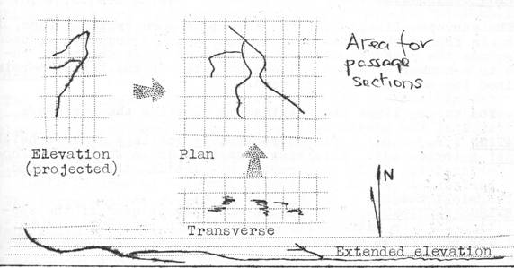
FIGURE 1.
Another common fault is can lead to a certain amount of
confusion, the placing of the views too close together in order to get all the
information on one sheet. The final
result will be a jumbled mess that is difficult to understand.
Many of the problems that the draughtsman will be faced with
at the start of his cave surveying career lessons as he becomes more
practiced in the art of drawing. Initially it is best to discuss the problems with experienced
surveyors who will provide him with many ideas and much food for thought.
One of the difficulties that the draughtsman will have to
face up to is the amount of information he can afford to add to his survey
without cluttering it. The quantity of
detail that he will be able to add will obviously depend of the scale at which
he is drawing the survey; too much will clutter the survey and make the general
presentation ugly. On the other hand a
survey with no detail or informative notes is of little use to anyone except
perhaps the surveyor himself. Collins
has pointed out that the surveyor/draughtsman has to bear in mind at all times
the reason for the survey. Once this is
clear in the mind some idea of the detail required can be determined; this may
well affect the scale at which the survey is to be drawn. Again there is no one solution to the problem
and only experience will show what balance is required. Accurate outline surveys on the other hand
are much simpler that the descriptive maps in as much that the required detail
is limited to passage outline and the essential notes as to the accuracy of the
survey etc.
Grid
All maps and surveys are overlaid with a grid that enables
the user to quickly locate passage junctions and other places of interest from
the written description or route severity diagrams of the cave. The reference numbers will be found inn the
text. The grid has a two fold purpose,
one already mentioned, the other to form the framework around which the
draughtsman can work to plot in the co-ordinates when drawing up the survey. For these reasons the grid must be accurately
drawn.
The grid on any survey or map has its origin off or on the
S.W. corner and so to keep to convention all cave surveys should be the
same. If the cave has promise of further
extension (and which one hasnt?) then place the point of origin some
considerable distance from the cave. In
the case of the new St. Cuthberts survey the grid origin lies 10,000ft. to the
west and 10,000ft. to the south a point (very near Westbury-sub-Mendip) that
takes in any survey made of the resurgence should the cave be found to have
open passage that far! By placing the
origin somewhere to the S.W. will avoid the need for negative co-ordinates
which if used will increase the chance of error in the calculations.
The quickest and easiest way of obtaining an accurate grid
is to purchase sheets of FLAT graph paper from drawing office suppliers. Remember that paper rolled during or after
printing will stretch in the direction off the roll. It is best to check the paper before
purchasing with a rule it has been found that the error can be as great as ¼
in 9!
To standardise presentation wherever possible the Mendip
surveyors have agreed to a standard 2½ square grid. This is not a hard and fast rule but a guide
as it will be realised that there are occasions when such dimensions are not
convenient.
Plotting Co-ordinates
The surveyed line, either in closed or open traverse form,
is the basic framework of the cave system that the draughtsman uses to produce
the passage outline. As all the views
are being reduced to a number of common planes only two of the three
co-ordinates obtained for each station are used.
PLAN The survey
lines are obtained by plotting the northings against the eastings.
ELEVATION (projected). Plot northings or
eastings against height.
ELEVATION (extended). This view cannot be
drawn wholly from co-ordinates. It is
constructed by plotting the calculated horizontal (which are usually summated
to each station) against height.
TRANSVERSEW SECTIONS Co-ordinates may only be used if the section lies on either the east-
west or north- south datums. The section
is constructed by drawing the projected lines against height.
Method
The co-ordinates have to be converted to fit the cave
grid. If the fixed point, which would
usually be at the closing point of the main traverse, in say 10,000ft. north
and 10,000ft. east is to say the fixed point for the cave lies 10,000ft. to the
north of the grid origin, then the summated co-ordinates are added or
subtracted to the fixed value. (see
fig.2)
The values of the heights from the fixed datum can remain as
the calculated values but their actual O.D. value can be worked out later when
required for entering the permanent survey stations onto the survey.
FIGURE 2
Preparing co-ordinates for plotting:
|
STATION No. |
CALCULATED |
CO-ORDINATES |
NORTHINGS |
EASTINGS |
|
|
Northings |
Eastings |
|
|
|
1 |
0 |
0 |
10,000.00 |
10,000.00 |
|
2 |
8.5 |
-6.47 |
10,008.50 |
9,994.53 |
|
3 |
9.56 |
-8.53 |
10,009.56 |
9,991.47 |
|
4 |
19.66 |
-.6.53 |
10,019.66 |
9,993.67 |
|
5 |
22.86 |
-27.53 |
10,022.86 |
9,972.47 |
Plan
Station 1 is positioned on the grid to suit the extreme
co-ordinates. This will ensure that
whole or part of the plan that is required will fit onto the grid that you have
drawn. Once the fixed datum point is
positioned, plotting of all the station points may begin. Station 2 is located by measuring 8.50ft.
above the datum line (best measured from station 1) and draw a horizontal line
through this point. Measure 6.47ft. to
the left of the datum line and draw a vertical line up through the horizontal
to obtain the point for station 2. Where
these two lines cross is the position for station 2. Repeat this procedure until all the stations
are plotted in. It will help the
plotting if you mark at the end of the grid lines the co-ordinate values at that
point (see fig. 3). All eastings with
values less than 10,000ft. will be plotted to the left of the datum line and
values greater than 10,000ft. are plotted to the right of the datum line. The northing values are manipulated in a
similar manner. A lightly drawn line
connecting each station point on the correct sequence will prove useful when
adding passage details.

FIGURE 3
Elevation (projected)
The simplest elevation is built up on the north-south or
east-west lines and for most caves this will suffice. If however an elevation is required along a
line say running N.W. S.W. then the co-ordinates will have to be recalculated
to suit the new projection line. This effectively relates all the bearings to
the required datum lines.
The basic method of drawing the elevation is as
follows. Fix the position of the fixed
point, bearing in mind the maximum and minimum heights of the cave relative to
this point. To plot Station 2 (assuming
the elevation is on the north south line in this example) measure the value
of the northing and plot it against the change in height. In the case of the projected elevation the
north south line will run from left to right of the paper if drawn on a
separate sheet. If however that is, is
being drawn on the same sheet as the plans then, as stated earlier, the
projection must, in its correct relationship with the plan; in this case the
north south lines will run parallel with the north south lines of the plan.
Station 3 is plotted in a similar manner as the previous
station by measuring off the northing value against the change on height at the
station. This is repeated for the whole
of the traverse. (see fig. 4).

FIGURE 4 PROJECTED
ELEVATION
It will be noticed that in projecting the passages from the
plan, the true lengths will not be shown and that this projection will distort
passage lengths and slopes. However, it
has the advantage that all features of the cave are in their correct
relationship with respect to each other.
Should only part of the system be required to be shown in
this form then the elevation or section should be entitled PART ELEVATION or
PART SECTION.
Extended Elevation
Before discussing the method of plotting the survey station
points a note on presentation is needed. Extended elevations are really special cases in as much as that the
other views are drawn in pre-determined limits, i.e., the extreme co-ordinates. The development of passages involves the
passage length which is a constant value but the various ways of presenting the
development can present a problem of which one is the best. It is advisable to make several layouts of
the extended elevation before adding it to the master drawing to ensure that
what is being shown will be clear to the user. In fact where difficult elevations are involved try the arrangement on
as many people as possible preferably the typical caver if he can understand
the layout then use this even though the draughtsman may feel it is not the
best method.
In the case of a complicated (from a surveyors point of
view) system, i.e. (Eastwater, Swildons and St. Cuthberts) a projected
elevation would be extremely difficult to show clearly the run of the major
passage as in many cases it would have to be shown as hidden detail (i.e.
other passages crossing in front of them) (see fig.5). In this event the extended elevation is the
ideal method to clarify the situation.

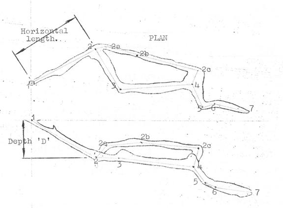
The method of plotting the main lines is as follows: – Plot
in the fixed datum point. Draw in the
horizontal distance between station 1 and station 2 and plot this against the
vertical change in height. Repeat this
for stations 2 and 3 by drawing the horizontal distance for station 2 to 3 and
plot against the vertical change in height. Continue with this procedure until the whole traverse (if this is all
that is required to show on this elevation) is completed. If the survey is to be simplified by the
omission of minor passages then this should be stated. This type of elevation ignores passage
direction but the true length of the passage is retained. In other words the
bends in the passages have been ignored and the passage has been pulled out straight. It must also be noted that any side passages
or chambers that are shown will not be in their correct relationship with each
other this fact must be stated on the drawing. An outstanding example of this method in use
is
extended elevation of Swildons Hole.
The extended elevation has the great advantage of being able
to straighten out a circular route in a cave and present it in a straight line
the ends of which is the point where the elevation has been broken. Where two passages run between the same
points one of these passages will be longer than the other. If these are plotted in the extended form the
shorter is broken at a suitable point and a note to the effect that no passage
length has been omitted. If on the other
hand, the shorter passage is best shown in full then the longer must be broken
and the length of passage omitted stated (see fig.6).
EXTENDED ELEVATION

PROJECTED ELEVATION
Transverse Sections
There are many occasions when a complete section of the cave
is necessary to gather the full picture of the shape and general position of
chambers and passages. Theses will be
drawn either above of below the plan depending on the direction that they are
being viewed and will be at 90o to the main elevation. In other words they will run on the east
west line if the elevation has been drawn on the north south line. The method of drawing the transverse section
will be similar to the elevated except that the eastings will be plotted
against the vertical changes in height. This type of section will only show the passage section at that point
chosen for the section of the cave through which the section line passes. If the cave is complex then several views of
this type will be required. To throw the passages out more clearly it might be
suggested that the passage shape be shaded or even blacked out (see fig.7).
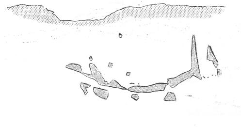
FIGURE 7.
to be continued.
BEC Items for
Sale
B.E.C. Car Badgess —— 17/6 ea. B.E.C. Ties
..17/6 ea.
The above items are available from Bob Bagshaw,
Knowle,
4.
B.E.C. publications are available from Bryan Ellis,
Knockauns, Combwich, nr. Bridgwater,
BELFRY BULLETINS (pre 238) are available from Dave Irwin,
3 at 9d ea. when available.
AUGUST ISSUE of the B.B. includes Part 2 of drawing of Cave
Surveys; review of James Lovelocks latest book Caving Ireland, 1969; and the
usual regular notices.
SEPTEMBER ISSUE includes Achnenschacht 1969, the Surveying
Unit;
October issue: Location of Errors (surveying); address list.
Other material in the pipeline includes Repair of Nife
Cells; Cave Photography; A Walk in
Repairs At The Belfry
The following
materials are required to repair the Belfry before winter. Stove pipe, glass, timber, tar and sand for
roof, toilet door and mattresses. If
anyone can help either by working or supplying materials free or cheaply please
contact the Hut Engineer (John Riley). If you have any spare time at the Belfry why not carry out a few
repairs? It may be some time before we get a new one.
A working weekend has been arranged for the weekend 6th/7th
September, the Belfry will be closed except to persons working. The response to the previous two working
weekends was almost nil, please give this one your support.
Route Severity Diagram
By S.J. Collins
PART 9. RIFTS, BEDS, DRAINPIPES and
SQUEEZES
Getting down to detail, it is possible to have many different
types of constriction as the tile of this part suggests. Since all are forms of constriction, we use
the basic sign for this throughout, but vary it as follows: –
If the passage is a RIFT, we use the basic constriction
sign. This will be a rift which is
sufficiently narrow that you cant quite travel down it without moving your
shoulders sideways a bit. If the rift
gets very narrow and you have to squeeze sideways through it, it is shown with
the constriction signs TOUCHING the other side of the passage. Thus we have: –
RIFT![]()
NARROW RIFT![]()
Beds are shown with the basic constriction sign in
BLACK. Thus a bed which involves hands
and knees crawling, or heavy stooping would be shown thus: –
![]()
while a flat out crawl type bed would be shown as a
narrow bed like this: –
![]()
A DRAINPIPE is a passage which is constricted in both
directions, so we draw both signs alternatively like this: –
![]()
and, of course, a tight drainpipe becomes
![]()
If we want to, we can show a passage which is very tight
vertically and moderately tight horizontally like this: –
![]()
.and equally well, the opposite
![]()
Localised squeezes are shown like this, for a vertical
squeeze (rift type)
.
![]()
and similar signs for a short horizontal squeeze (bed type)
and for a hole.
Bed type squeeze ![]()
Tight hole ![]()
PART 10. CHIMNEYS, RIFT PITCHES AND
RIFT TRAVERSES.
Continuing our look at detail possible with the signs of the
R.S.D., we saw at an earlier stage that we could combine the sign for tightness
with that for a pitch to produce a tight pitch. A chimney is a vertical drainpipe, so we can show a chimney like this,
if we need tackle (it might be fairly tight but still need tackle owing to
smooth walls, widening drop underneath it etc.).

..or a climb up or down a tight chimney like this: –

If a pitch is only constricted in one dimension, we show it
as a rift pitch like the entrance pitch to Cuthberts and the sign is show
below left, or for a tight rift pitch the sign is show below right.


to be continued.
For Your Diary
Club activities including the
CAVING PROGRAMME for further details contact Andy
MacGregor, John Riley or Dave Irwin.
Sat. Aug. 2nd. –
South
O.F.D. II.
Sun. Aug 3rd. –
Committee Meeting, 2.30pm, Hunters.
Tues. Aug 5th. – St.
Cuthberts Dining Room Dig. 6.45pm.
Thurs. Aug.7th. –
Waggon,
Sat. Aug. 9th. –
St. Cuthberts Cerberus Rift (w.t.) & D.B.
Sun. Aug 10th. – East
Twin Swallet digging
Tues. Aug 12th. – St.
Cuthberts Dining Room Dig. 6.45pm.
Thurs. Aug.14th. –
Waggon,
Sat. Aug. 16th. – St.
Cuthberts Tracing Coral Stream (further details from Roger Stenner and Dave
Irwin.
Sun. Aug 17th. –
Dining Room Dig, Dam building and checking water samples of Coral Stream
Tues. Aug 19th. –
Dining Room Dig, St. Cuthberts
Thurs. Aug.21st. –
Waggon,
Sat. Aug. 23rd. – St.
Cuthberts Dam building, Rabbit Warren Extension (w.t.)
Sun. Aug. 22nd. –
Dining Room Dig and Dam building.
Tues. Aug 26th. – St.
Cuthberts Dining Room Dig. 6.45pm.
Thurs. Aug.28th. –
Waggon,
EVERY WEDNESDAY –
Digging in the Chepstow area, further details from Roy Bennett,
Westbury-on-Trym,
Another programme for August/September period in the August
B.B.